Diagnostics of generator rotors and end-winding retaining rings
Diagnostics of rotors’ metal
Rotor shafts of power generators at thermal and nuclear power plants operate in complex stressed conditions under cyclic loads. So upon the long-term operation there is a possibility of their damaging with severe consequences due to the metal fatigue. However until recently (as of January 2008) no recommendations and techniques for inspection of the generator shafts metal existed in the TPS and NPS.
Energodiagnostika Co. Ltd. has the experience in application of the metal magnetic memory (MMM) method during the metal’s state inspection of PT-60, T-100, K-200 and K-300 turbine generator shafts. As the experience of the rotors inspection shows, the shaft necks are the most susceptible to damaging zones.
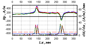
Fig.1 shows the distribution of the Hp magnetic field, recorded during the inspection along the shaft neck under the bearing # 7 of the K-200 generator at Zainskaya TPS.

Fig.1. The distribution of the Hp magnetic field, recorded during the inspection along the shaft neck under the bearing.
The zones of the abrupt local variation of the Hp field and its gradient dHp/dx correspond to stress concentration zones. If the damaged metal layer is not timely removed in the stress concentration zones by ordinary grinding during the repairs, the intensive development of fatigue cracks is possible in these zones.
Diagnostics of generator end-winding retaining rings
In the course of turbogenerators operation defects occur on the end-winding retaining rings, which, if not timely removed, tend to develop and may cause serious accidents. At present the major measure to ensure reliability of the end-winding retaining rings consists in marginal inspection by the non-destructive methods and examination of the internal surface after their removal from the rotor.
Energodiagnostika Co. Ltd. has the technique for inspection of the end-winding retaining rings’ state without their removal from the generator shaft. Besides, the technique allows carrying out the assessment of the end-winding retaining rings fit tightness after their shrink fit during the repairs.
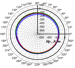
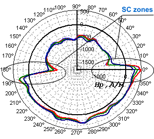
Fig.2 shows the inspection results of an end-winding retaining ring located on the side of the K-200 generator rotor half coupling.
 |
 |
|
Fig.2a. The results of an end-winding retaining ring inspection in the section remote from the fitting place. |
Fig.2b. The results of an end-winding retaining ring inspection in the section coinciding with the place of its shrink fit on the rotor. |
The inspection results, shown in fig.2, a, characterize the satisfactory state of the end-winding retaining ring in the section 2, being remote from the fitting place. Fig.2, b shows the magnetogram recorded on the same end-winding retaining ring in the section, coinciding with the place of its shrink fit on the rotor. The abrupt local variations of the Hp field correspond to the stress and strain concentration zones. The damages develop exactly in these zones on the internal surface of the end-winding retaining rings.