Diagnostics of shroud ties of steam turbine blade system
Reliability of blades collected in pack with shroud strip depends to a considerable extent upon stress-strained state of a strip itself.
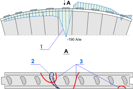
Fig.1 shows the testing results of the shroud strip of one of the blade pack of the stage №20 of the turbine T-100-130 of Severodvinsk thermal power plant-2. Fig.1,a shows the field Нр distribution registered along outlet edge of the shroud strip, while fig.1,b shows the SC lines stipulated by jamming of shroud strips of neighbour packs in U-shaped joints. The blade on which the crack was disclosed under testing of the present pack is indicated by dotted line on the same fig.1,b.

Fig.1. The testing results of the shroud strip: 1- the field Нр distribution along the outlet edge of the shroud strip; 2 – the blade with detected crack; 3 – SC lines stipulated by jamming of shroud strips in U-shaped joints.
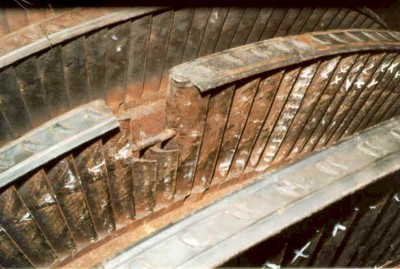
Fig.2 presents the example of the blades and shroud strip failure due to deficit of thermal compensation.

Fig.2. The example of the blades and shroud strip failure due to deficit of thermal compensation.
Analogous blades damages can occur due to jamming in solid-milled shrouds applied on disks of large diameter (turbines of types: PT-60, K-200 and others). Damper ties in shape of wire or tubes widely used for the last stage blades shall be compliant enough to fit tightly to the blade under centrifugal force action and at the same time they shall be rigid enough to have a necessary strength. It is impossible to provide such optimal conditions without effective method of inspection of stress-strained state of the damper wire itself. Application of the metal magnetic memory method allows to solve this problem on practice.